Energy Analysis
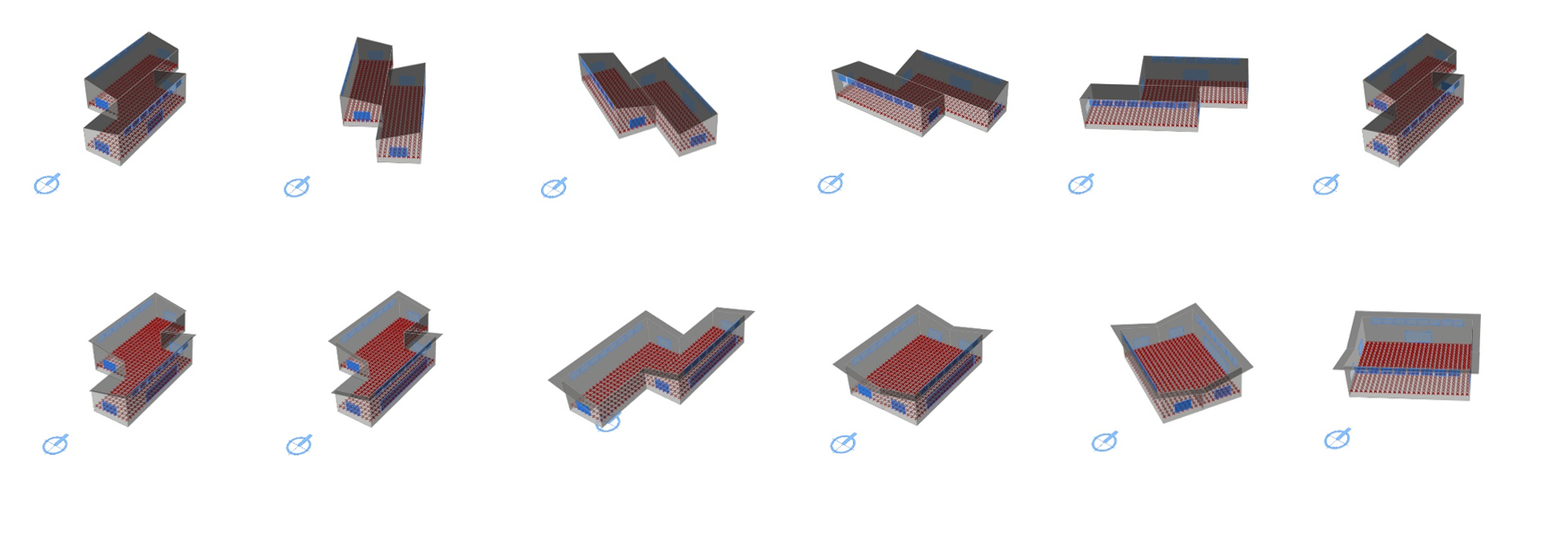 Figure 3.1: Energy analyses of Sprout Space alternatives.
A n energy simulation calculates the heating and cooling energy required to keep the building at a comfortable temperature throughout the year (typically this means keeping the building between 19 C and 26 C). Before running the simulation we need to define the attributes of each room in terms of their adjacency, internal loads, occupancy scheduling, and the material properties of the room.
Energy simulation uses details of the spaces, building constructions, and weather data to calculate the temperature inside each room for every hour of the year (8760 hours) to calculate the heating and cooling energy required to keep the temperature inside each room comfortable when people are using each room.
The Honeybee and Ladybug components for Grasshopper used in this tutorial are simply an interface to an engine called EnergyPlus, version 8.5.0, which does the calculations described above. The Honeybee + Ladybug specific installation instruction can be found here.
The OpenStudio component used in this tutorial also interfaces with EnergyPlus and Radians. In addition, the OpenStudio multi-platform adds a Software Development Kit (SDK) that enables extension and customization. Detailed information can be found here
Resources
| Resource | Description | Weblink | |
|---|---|---|---|
| EnergyPlus 8.5.0 | Energy Simulation Software | Download | |
| Ladybug 0.0.63 + Honeybee 0.0.60 | Energy, Daylighting and Lighting Simulation | Download | |
| OpenStudio 1.14.0 | Interfacing with EnergyPlus and Radiance | Download | |
| GH file | Sprout Space GH Energy Analysis Definition | Download | |
| epw file | Weather Data, Los Angeles, CA | Download | |
| Python 0.6.0.3 | Python Interpreter for GH | Download |
Setting the model up
When we run an energy simulation we actually call rooms in a building zones. While a room is just geometry, a zone has many more attributes, including the amount of lighting W/m2, the number of people and the equipment in the zone. These three attributes cause heat gain (W/m2) in the zone which will affect the final heating and cooling load of the zone.
A compressed example workflow is shown below, while the next sections will detail the Energy Modeling section of the Sprout Space workflow.
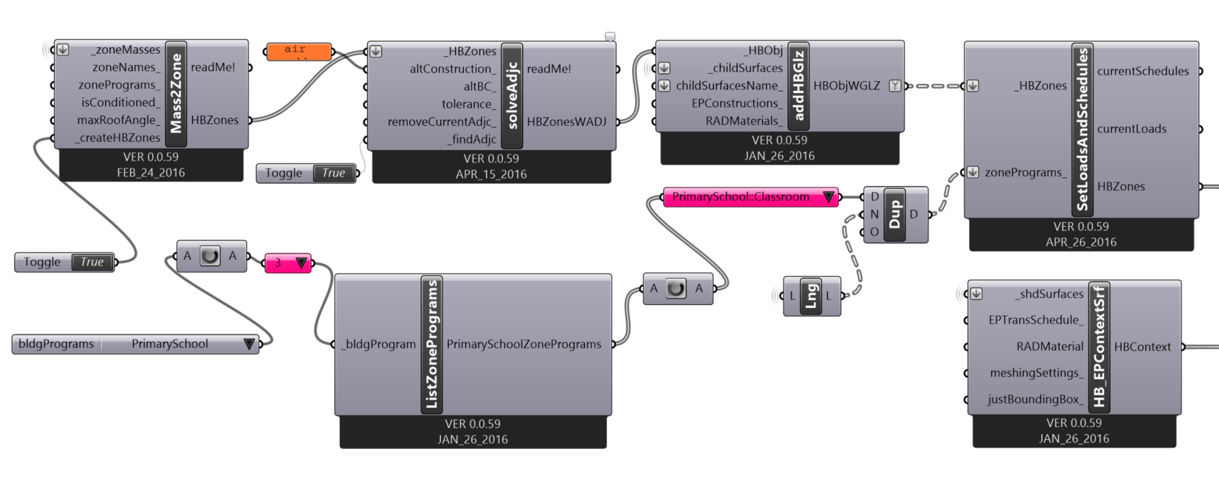
*Figure 3.2: An example workflow (Not SproutSpace workflow) showing how Grasshopper Breps (Boundary Representations) can be taken and converted to Honeybee zones, this workflow is more compressed than seen in the SproutSpace Grasshopper file. The components here are represented by their names and not their icons unlike in the Sprout Space workflow shown below
Convert Mass to Zones
The component Mass2Zones (Figure 3.3) converts Grasshopper Breps to Honeybee zones if the toggle button is true (Figure 3.3). As described above the B-rep can be thought of as a room while a Honeybee Zone is simply a zone.
 Figure 3.3: Mass2Zones component

*Figure 3.4: The resulting representation of the geometry of a Honeybee Zone
Zone Adjacencies
When different zones are placed adjacent to each other (meaning that the geometry of one zone is touching the geometry of another zone) heat and air is exchanged between the zones resulting in heating and cooling loads (measured in W/m2) in the zone. For this reason we must solve to find which zones are directly adjacent to one another. The solveAdjc component does this.
Figure 3.2 shows that the solveAdjc component is placed after the Mass2Zone component, because after geometry is converted to zones, the adjacencies must be found for each zone.
Add Glazing Surfaces
Unless zones are basements or data centers they should have windows. The addHBBGlz component takes window geometry in the input childSurfaces and, if the window geometry is co-planar to the walls and roofs of a zone passed into HBObj, the windows are added to that zone (Figure 3.4).
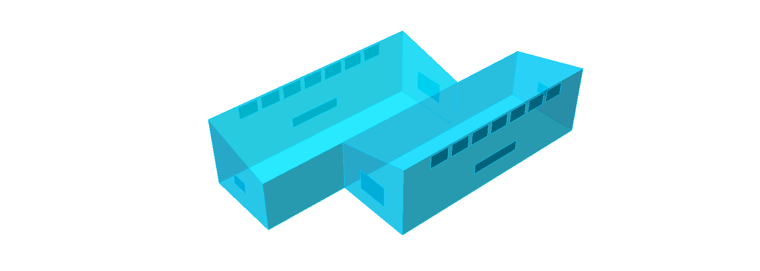
Figure 3.4: Visualization of the Honeybee zones once windows are added
Loads and Schedule
The SetLoadsAndSchedules component enables setting the zone schedules (Figure 3.5) for when occupants come and go and leave the zone, for when lights are turned on and off, and for when heating cooling and ventilation is turned on and off.
These schedules are combined with the amount of lighting, equipment and number of occupants in a zone, resulting in a heat gain (measured in per W/m2) over the time period of the schedule. This heat gain heats the zone and is used later to determine the heating and cooling required to keep the zone within a comfortable temperature.
This component is inheriting default schedules and figures from the component listProgramZones which is providing a default "program" for a primary school, which was created by the Department of Energy.
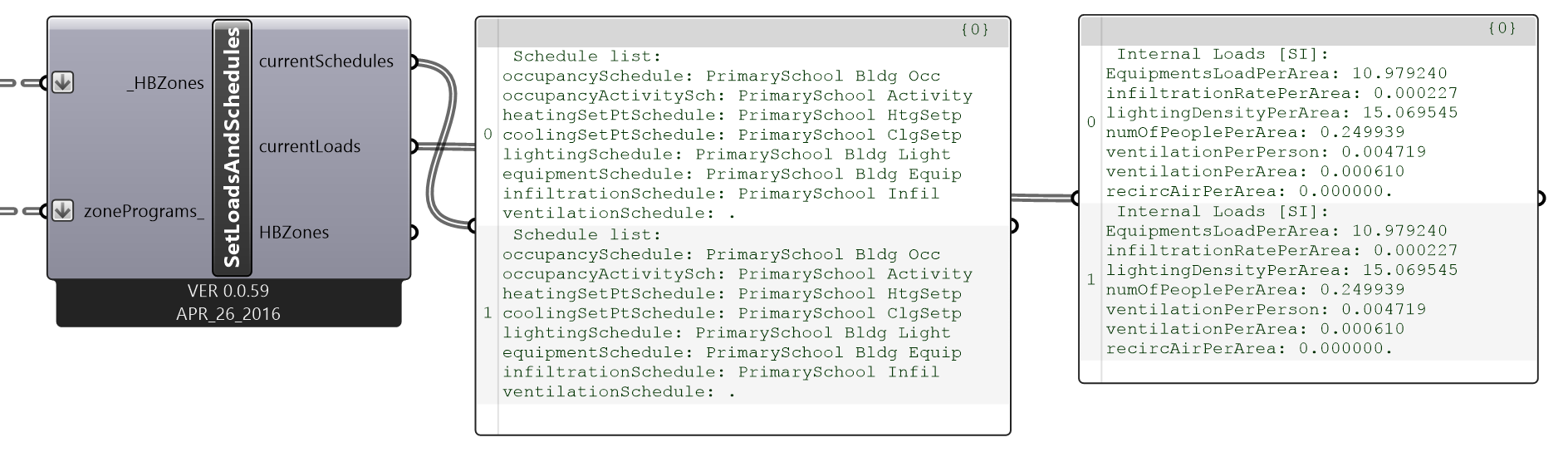 Figure 3.5: Schedules and loads
Set Ventilation and Air Change Rates
These two components are used to set the amount of ventilation in each zone. One component ACH2m3/s-m2 is used to calculate the infiltration rate in the zone. Infiltration is the air change in the zone due to leaks from cracks and doors etc. This is usually a very difficult number to quantify without measuring it with blower door tests and so by default it is set to 0.6 air changes per hour.
The component ACH2m3/s-m2 calculates how much air is required in m3/s-m2 in order to achieve a air change rate of 0.6 air changes per hour by infiltration for each zone. This number is then plugged into the infiltrationRatePerArea input on the component setEPZoneLoads which then sets the infiltration for each zone. The ventilationPerArea and ventilationPerPerson rates for each zone are also set by the setEPZoneLoads component as seen in the Grashopper file. These rates are taken from ASHRAE 62.1. All other inputs not set on setEPZoneLoads have been set by the default program for a primary school by SetLoadsAndSchedules.
Set Zone heating and cooling set points
The setEPZoneThersholds component sets the temperatures at which both rooms are conditioned to. Cooling will be used when the temperature is too high to bring it back to the cooling set point temperature (26 C), while heating will be used when the temperature is too low to bring it back to the heating set point temperature (18 C).
Context Shading Surfaces
In both Daylighting and Energy simulations there will often be context surfaces that are not part of the zones that we created, but that shade the zone none the less and thereby affect the zone's heating and cooling loads. These surfaces are added to both simulations by the HB_EPContextSrf component.
Constructions
This section corresponds to the specification of the attributes and values of the building materials (Figure 3.6) that determine the energy flow through the envelope of the building.

Figure 3.6: Set construction process and main components
Set Constructions
To finish adding the information about zones, we must also describe the materials which enclose the zones using the component setEPZoneCnstr. This component assigns materials to the walls,windows,roofs,skylights and floors of the zones. The properties of these materials describe the U-value of the material (W/m2 K), and are used in the energy simulation to determine the heat transfer in and out of the zone (in W/m2), which will affect the heating and cooling load.
With regards to daylighting the component setRADMaterials is used to set the color (in RGB values), roughness (0 to 1 scale) and reflectance of the finishes inside each zone as well as the transparency (0 to 1 factor for the blue,red and green spectrums) of the windows.
Decompose Model into Components
The decomposeByType node decomposes the model into components. If the selected only preview is turned on, you can visualize the different components (Figure 3.7) of the model
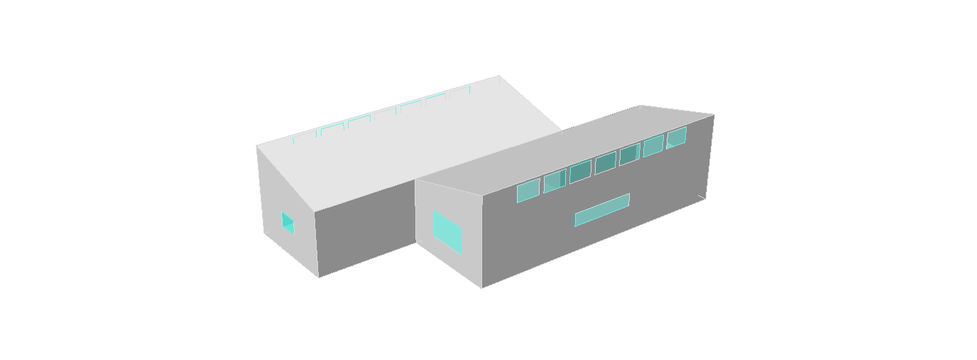
Figure 3.7: An Example visualization of the opaque and glazing surfaces
Energy Simulation
The Energy Analysis section (Figure 3.8) calculates the heating and cooling energy required to keep the building comfortable.

Figure 3.8: Energy simulation process and main components
Weather File
The Open weather file component imports an epw weather file (Figure 3.9) as a string which provides weather data (temperature, humidity, etc.) for every hour of the year. Save the file in any local folder. Avoid Box or Dropbox folder since their encryption creates conflicts while Ladybug plugin reads it.
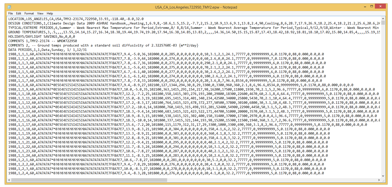
Figure 3.9: Content of the epw weather file
Run Simulation
For the energy simulation the exportToOpenStudio component interfaces with EnergyPlus and writes all the geometry and relationships that were entered into the components above. This information, along with the weather file information, calculates the temperature of the room in the building for every hour of the year. If the temperature is too high or low, heating or cooling is used to make the temperature comfortable, and energy use required for each zone can be calculated.
Read Results
The outputs computed by the runEnergySimulation component can be seen through the readEPResult in terms of kW/h (Figure3.10).
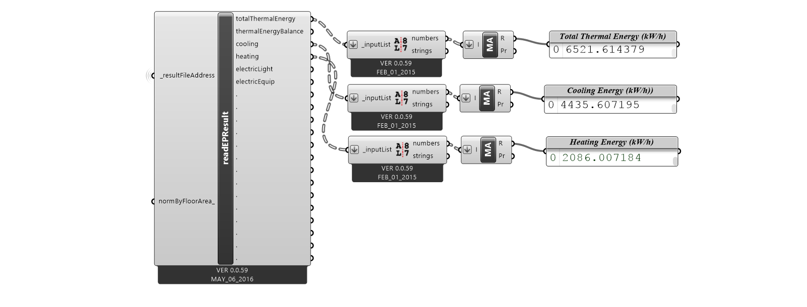 Figure 3.10: Cooling, Heating and Total Energy Consumption in kW/h