Alternative Generation
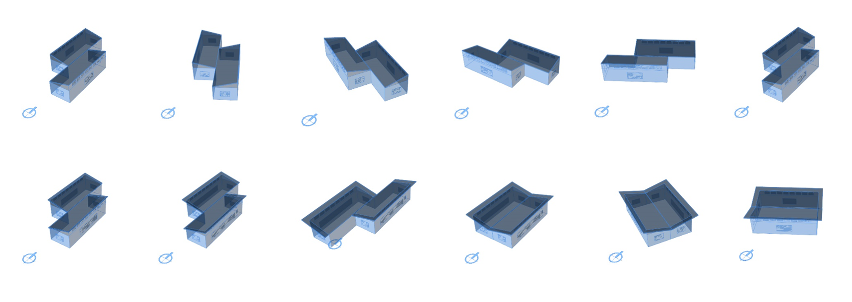
Figure 2.1: The Sprout Space Computational Design Space of Many Alternatives
A design alternative consists of a selected group of options for every input decision variable.
This section introduces a simple parametric model that creates Alternatives with geometric and other outputs suitable for analysis. The project uses a definition script file written in the visual graphical language of Grasshopper for Rhino. Grasshopper is easy to learn and use, and can drive an environment for collaboration. The script generates Sprout Space alternatives consisting of project geometry, material, and building system options. Subsequent chapters analyze and then decide among these alternatives.
Resources
| Resource | Description | Weblink | |
|---|---|---|---|
| Grasshopper plugin | Parametric Modeling for Rhinoceros | Download | |
| Elefront plugin | Improves Interaction with Rhino | Download | |
| Human plugin | Extends Access to Rhino Elements | Download | |
| Tree plugin | Improves List Management | Download | |
| MetaHopper plugin | Dynamic Manipulation of GH Script | Download | |
| Lunchbox plugin | GH Modeling Resources | Download | |
| GH file | Sprout Space GH Parametric Model Definition | Download |
Conceptual Model for Analysis
The conceptual parametric model provided represents with simple geometry (Figure 2.2) the fundamental features required by the analyses. The Sprout Space Generator cluster (Figure 2.3) uses mainly single surfaces to represent walls, floors, roof, windows and overhangs rather than fully over detailed objects. The analyses attaches the necessary material properties to run the evaluations to each of those surfaces. Generally, when constructing a parametric model, a modeler strives to be complete in terms of representing all the objects required by the analyses (nothing less, nothing more), general enough to represent the design space of alternatives, effective in order to support the geometric variations and efficient in terms of the use of computational resources.
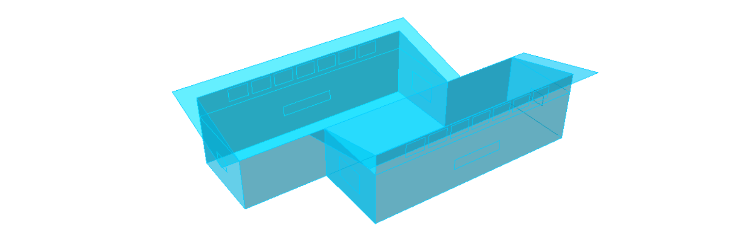 Figure 2.2: The Sprout Space Conceptual Model

Figure 2.3: Sprout Space Generator cluster
Input Parameters
Several input geometric parameters from the problem formulation drive variations of the model. The variables are organized in four groups that control the building massing, windows, roof and clerestory.
Building Parameters
The basic building block for the project consists of two similar classroom bars that join and share a common wall with an offset. The script provides fine control over the classroom net area with width, length, height and offsets (Figure 2.3). A single parameter provides for the classroom block to rotate with respect to the true north area with a desire for pursuing glazing, self-shading strategies, or other goal-oriented reasons for use of this feature.

Figure 2.3: Basic building configuration parameters
Windows Parameters
The model uses a set of sliders to vary fenestration geometry, with independent control of the left and west window to wall ratio (Figure 2.4). A final control for envelope wall thickness allows for more detailed geometry generation capabilities that are required by the view quality analysis.

Figure 2.4: Fenestration and Envelope Thickness Parameters
Roof, Fascia, and Overhang Parameters
The project uses single sloped roof geometry for each class room bar (Figure 2.5). The overhang depth variable provides a variable feature for self-shading and aesthetics. The roof fascia geometry parameter delivers additional geometric variation.
 Figure 2.5: Roof, Fascia, and Overhang Depth Parameters
Clerestory and Pane Parameters
The project features a clerestory design option for delivering natural daylight into the class room spaces. The parameters define the width, and height (Figure 2.6). Clerestory spacing and number of panes parameters provide control over the geometry generation.
 Figure 2.6: Clerestory Geometry Parameters
Output Building Components
Next, the parametric model decomposes the simple conceptual geometry into building objects that are required by the different analyses.
Zone Masses
The conceptual model represents the spaces of the building as closed boundary representations (b-reps) that will be taken by the Mass2ZoneHoneybee component. This component adds all the required properties and setting for surfaces, schedules and loads and HVAC systems that are required to perform the analyses.
 Figure 2.7: Closed b-reps objects representing the classroom spaces
Windows
These surfaces are required to add the glazing areas of the front, side, and clerestory windows to the zones (Figure 2.7), with the proper material properties such as U-value and Solar Heat Gain Coefficient (SHGC).
 Figure 2.8: Glazing areas
Shading Surfaces
Shading surfaces compute areas of the building under direct solar radiation. The HB_EPContextSrf Honeybee component specifically requires non-convex surfaces for more accurate results. For non-convex shapes, such as in Figure 2.9, splitting the shading area in at least three four-sided surfaces is recommended.
 Figure 2.9: Shading areas
Partitions
The partitions are required to subdivide the space in order to properly calculate the dark areas of the building that have no exterior view, when performing the quality view analysis.
 Figure 2.10: Partition between zones of the building
Envelope Geometry
Similar to Figure 2.2, the view quality analysis needs the complete geometry of the envelope of the building including walls as closed planes with co-planar windows, roof and floor to identify the glazing areas required to perform the analyses.
Design Alternatives Generation
The Sprout Space Generator aggregates single or multiple alternative inputs, and routes it to the appropriate analysis workflows.
Generation of a Single Alternative
The use of individual set of parameters provides for a single design alternative. A single alternative groups all of the options for the class room geometry, fenestration, roof, overhang, envelope, and orientation parameters. Since most analyses engines require SI units, the conversion of imperial into SI unit is recommended. In this regard, Figure 2.14 shows such a conversion into meters by multiplying the imperial units by a conversion factor.
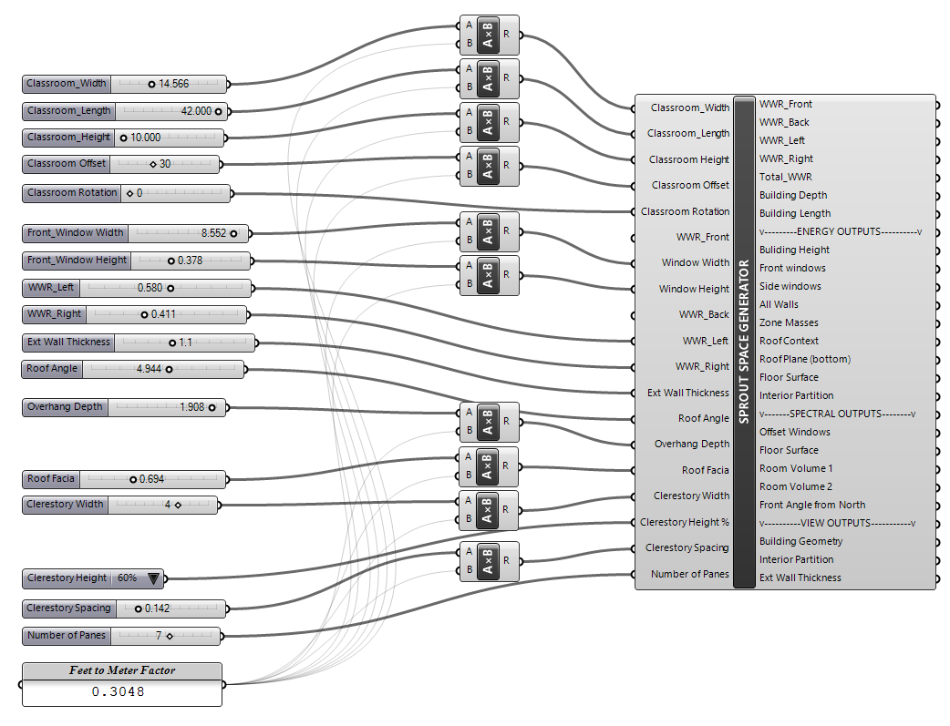 Figure 2.14: Parameters for a single alternative
Generation of Multiple Alternatives
The Sprout Space Generator provides an efficient workflow for entering multiple options for a unique parameter, and for very large design space exploration. Each single option is sent for analyses in a sequence. The number of options can easily exceed hundreds of iterations, so the feature should be used judiciously.
Figure 2.15 shows an example of the automation process of the window width variable. The variable has a list of three possible options indexed from 0 to 2. The variable ranges from 1' to 3', and is converted into meters by a conversion factor. The Item component pulls out a different option from the list every time the Index of Window With Option slider is automatically updated by the FLY! component that is triggered if the Automation Toggle is True. If the toggle button is False, then the selected option will remain as a constant. This process applies to automate the exploration of every variable.
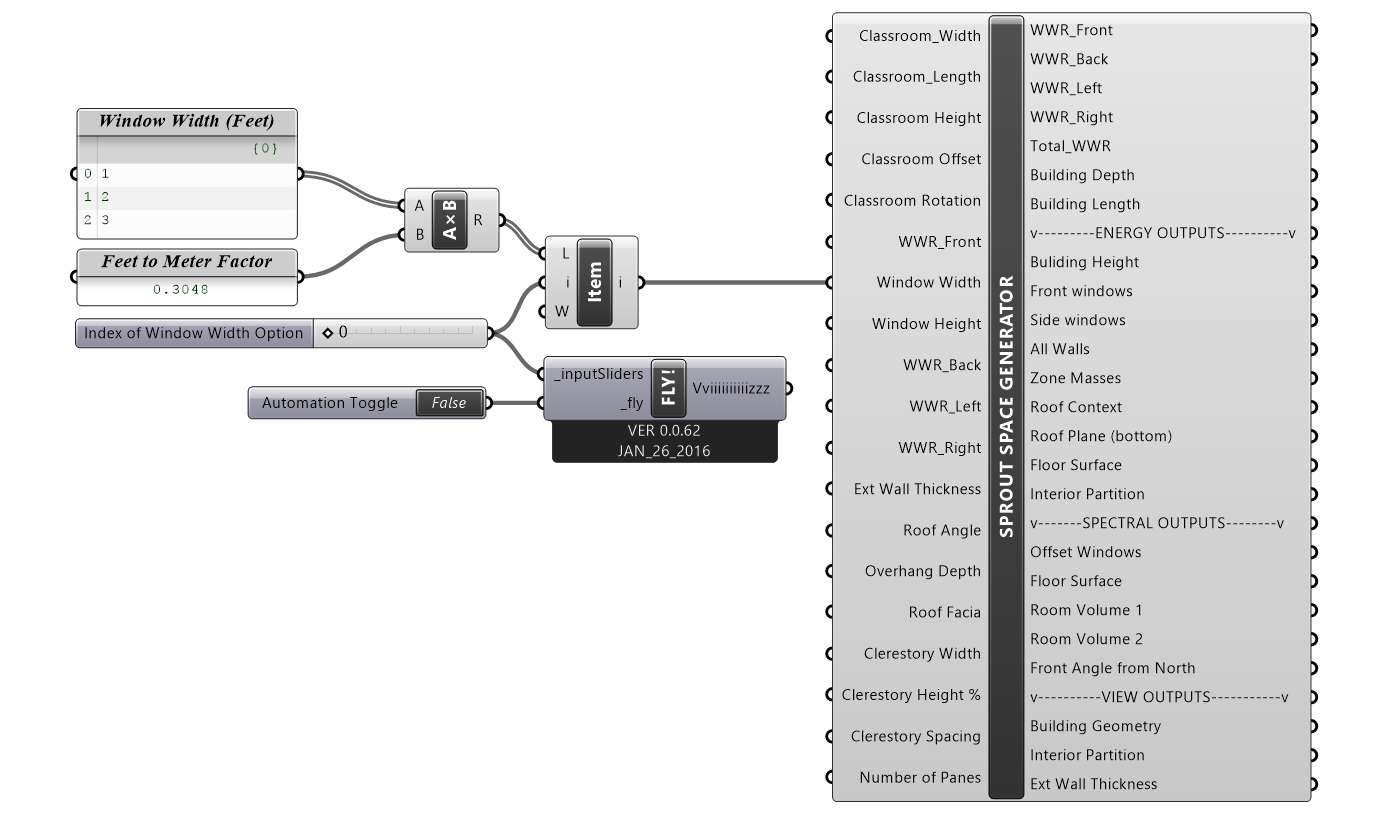
Figure 2.15: Automation of multiple options per variable
Design Space Matrix
The above automation process creates all possible combination of variables. A simple example shows two variables that have a mix of variables (Table 2.1). The first variable uses a set of values from 'a' to 'c' . The second one contains values from '1' to '3'. The combination of these two variables creates a matrix which is a set of rows and columns. This matrix is expressed as a '3 x 3' set . The total possible combination for this set of variables is a design space of a list of nine runs (Table 2.2). The design alternatives and the FLY! component works in this way to create potentially thousands of options.
Table 2.1: Matrix of variables
| Variable 1 | Variable 2 |
|---|---|
| a | 1 |
| b | 2 |
| c | 3 |
Table 2.2: Iteration run design set
| Iteration | Design Space |
|---|---|
| 1 | a,1 |
| 2 | a,2 |
| 3 | a,3 |
| 4 | b,1 |
| 5 | b,2 |
| 6 | b,3 |
| 7 | c,1 |
| 8 | c,2 |
| 9 | c,3 |